#esp32 datasheet
Explore tagged Tumblr posts
Visit Tumblr Blog
Explore Tumblr blogs with no restrictions, modern design and the best experience.
Last Seen Tumblr Blogs


Fun Fact
Hackers stole 65M passwords from Tumblr in 2013.
Text

Another 2022-present portable computer thing. This is a 1991 Corvallis Microtechnologies PC5-L. It's a ruggedized, waterproof handheld MS-DOS computer meant for industrial applications. It ran on Ni-Cd batteries and they died so now it runs on AA's I got two of them for $50 on eBay during one of those months when i impulse buy obscure electronics as a form of escapism This thing is an absolute brick. You could murder someone by hitting them on the head with this, and it would work fine afterwards. Here's pictures of its organs for anyone curious:


That thick red wire around the screen PCB is a heater. Yep there's a setting to heat up the LCD so it doesn't get sluggish or shatter when you decide to leave it in the freezer. The thing runs on a little system-on-chip thing, which is interesting to see coming from the early 90's. Iirc the datasheet says it's capable of analog video out as well as driving the LCD, but I haven't poked around enough to enable it. Might be cool to hook it up to a TV. I did, however, open those 512k storage modules and I saw some unpopulated footprints on the boards. So I ordered some of the same chips, and at some point I'mma try soldering them on and see if it recognizes the extra space. They came with two voltmeter modules, which I couldn't get to work, so I took one of the casings and made it into a USB and WiFi adapter using an ESP32 running Zimodem, since this thing has RS232 ports on the top. I also made my own charging adapter, since they didn't come with one. I see that internal PCMCIA slot, and I tried putting a CF card adapter in, and tried installing the drivers, but it didn't work. I'm not good at DOS tbh, and I know nothing of what this slot is for. I might come back to it later. I did all of this in 2022-23 and haven't messed with it since. Except to use it to talk to my Kaypro 4 '84:

More on that one later. I love portable computers !!!!!
101 notes
·
View notes
Text
ICN6211 & TFT display hacking debugging
yesterday we had the square 4" 720x720 TFT display working with our Raspberry Pi DTO + ICN6211 configuration. now we want to move onto a round screen. one thing that was kinda nice about that screen is it does not require an SPI init code - it pops up immediately into RGB TTL mode. all our other screens require configuration. which means now we have a lot of variables: the DTO and kernel driver that writes DSI data, the ICN6211 configuration that sets the TTL resolution and sync, and the SPI config. that's a lot of variables! we're going to back up and just make sure the SPI init is good - to do that we use the ST7701 datasheet to find the 'all pixels on' command. by sending this at the end of the init string and seeing all white display we know that at least that part of the configuration is working, then we can work back and get the ICN6211 test colorbars and finally work all the way back to the DTO setting. display work is really hard but this is something we've done many many times so we are used to juggling so many configs. what really helps a ton is having a known good setup using the ESP32-S3 Qualia, so we are really glad we got that working first
1 note
·
View note
Video
youtube
Smart QR-Code Based Door Lock System Using ESP32-CAM \Wi -Fi Door Lock System Using ESP32 CAM Based on IoT | IoT Operated Door Lock using ESP32 CAM Module | ESP32-CAM Face Recognition Door Lock System | IoT based Door Access Control System using ESP32cam | esp32-cam face recognition door lock system | face recognition door lock system using esp32-cam ppt | WiFi door locking System using ESP32 project report | esp32-cam face detection door lock system ieee paper***********************************************************If You Want To Purchase the Full Working Project KITMail Us: [email protected] Name Along With You-Tube Video LinkWe are Located at Telangana, Hyderabad, Boduppal. Project Changes also Made according to Student Requirementshttp://svsembedded.com/ https://www.svskits.in/ http://svsembedded.in/ http://www.svskit.com/M1: 91 9491535690 M2: 91 7842358459 We Will Send Working Model Project KIT through DTDC / DHL / Blue Dart We Will Provide Project Soft Data through Google Drive1. Project Abstract / Synopsis 2. Project Related Datasheets of Each Component3. Project Sample Report / Documentation4. Project Kit Circuit / Schematic Diagram 5. Project Kit Working Software Code6. Project Related Software Compilers7. Project Related Sample PPT’s8. Project Kit Photos9. Project Kit Working Video linksLatest Projects with Year Wise YouTube video Links152 Projects https://svsembedded.com/ieee_2024.php133 Projects https://svsembedded.com/ieee_2023.php157 Projects https://svsembedded.com/ieee_2022.php135 Projects https://svsembedded.com/ieee_2021.php 151 Projects https://svsembedded.com/ieee_2020.php103 Projects https://svsembedded.com/ieee_2019.php61 Projects https://svsembedded.com/ieee_2018.php171 Projects https://svsembedded.com/ieee_2017.php170 Projects https://svsembedded.com/ieee_2016.php67 Projects https://svsembedded.com/ieee_2015.php55 Projects https://svsembedded.com/ieee_2014.php43 Projects https://svsembedded.com/ieee_2013.php1500 Projects https://www.svskit.com/2025/01/1500-f...***********************************************************1. ESP32CAM QR Code Reader | ESP32-CAM-QR Code Scanner,2. DIY Smart Wi-Fi Video Doorbell using ESP32 and Camera,3. ESP32 CAM Face Detection Door Lock System,4. ESP32 CAM Face Recognition Door Lock System,5. ESP32 Cam Motion Alert | Send Image to Telegram,6. ESP32-CAM Face Recognition for Access Control,7. How I Build Face Recognition Door Lock,8. ESP32CAM QR Code Scanner,9. ESP32-CAM Face Recognition and Video Streaming with Arduino IDE,10. ESP32CAM QR Code Reader | ESP32-CAM-QR Code Scanner,11. ESP32-CAM Video Streaming and Face Recognition with Arduino IDE,12. WiFi Door Lock using ESP32 CAM
0 notes
Text
Power Supply for Espressif Module with Battery Charger & Boost Converter
We will discuss the integration of a power supply for the ESP32 Board. Additionally, we will add a Boost Converter Circuit to enable the use of a 3.7V Lithium-Ion Battery for powering the ESP32. Since Lithium-Ion Batteries can discharge, we will integrate a Battery Charger Circuit along with a Battery Management System. Many Lithium-Ion/Lithium Polymer Batteries can only charge up to 4.2V, which is low for the ESP32 Board.
Therefore, we need to increase the battery voltage from 2.8V-3.7V to 5V. This necessitates the use of a compact Boost Converter Module build with inductors, ICs, and resistors. To facilitate battery charging and management, we will use the TP4056 Battery Charger Module. Alternatively, we can also power the circuit using a 9V/12V DC Adapter. The LM7805 Voltage Regulator IC restricts the voltage to 5V. If you are not going to use a battery for power, you can utilize the DC Power Adapter or a 9V Battery.
ESP32 Power Requirement
The ESP32 Board’s operating voltage is between 2.2V to 3.6V. But we can supply 5V from the Micro-USB port. For applying 3.3V there is already an LDO voltage regulator on the module to keep the voltage steady at 3.3V. ESP32 can be powered using Micro USB port and VIN pin (from external supply).
The power requirement of ESP32 is 600mA of that ESP32 pulls only 250mA during the RF transmissions. When it is performing boot or wifi operation it’s drawing more than 200mA current. Thus supplying power from Micro-USB Cable is not enough for ESP32 Board when we need to add multiple sensors or modules to the Board. This is because Computer USB port can provide less than 500mA of current. Check more on power requirements of ESP32 here ESP32 Datasheet.
Hardware Requirements
Following are the components required for making this ESP32 Power Supply project. You can get all the components from our Campus Component store.
ESP32 Board-ESP32 ESP-32S Development Board (ESP-WROOM-32)
Battery Charger Module-TP4056 5V,1A Battery Charging Module
Voltage Regulator IC-LM7805 5V IC
Female DC Power Jack-DCJ0202
Step-Up Boost Converter Module-3.7V to 5V Boost Converter Module
Switch-3 Pin SPDT Switch
Electrolytic Capacitor-470uF, 25V
Electrolytic Capacitor-100uF,16V
LED-5mm LED Any Color
Resistor-220 ohm
3.7V to 5V Step-Up Boost Converter Module
The above shown is the Step-Up DC-DC Boost converter module which provides 5V DC stable voltage output for various input ranges between 1.5V to 5V. This small tiny circuit boosts the voltage level and provides the amplified stabilized 5V output. This module operates at a frequency of 150KHZ. It utilizes varying amounts of current to generate a balanced output for different input ranges.
Read more about Boost Converter
1. Input 1-1.5V, output 5V 40- 100mA
2. Input 1.5-2V, output 5V 100-150mA
3. Input 2-3V, output 5V 150-380mA
4. Input more than 3V, output 5V 380-480mA.
TP4056 Battery Charger Module
The TP4056 module is designed specifically for charging rechargeable lithium batteries through the constant-current/constant-voltage (CC/CV) charging technique. Apart from ensuring the safe charging of lithium batteries, the TP4056 BMS Board incorporates essential protection mechanisms for lithium batteries. It is compatible with both USB power and adapter power supplies. Also because of its internal PMOSFET architecture and anti-reverse charging path, there is no need for external isolation diodes.
TP4056 Module Datasheet.
Power Supply for ESP32 with Battery Charger & Boost Converter
The circuit can be powered by using two methods, one with 9V/12V DC Adapter and other with 3.7V Lithium-Ion Battery.
To power the board through the DC Jack, we've added here a DCJ0202 Female Jack. Also we have added 470uF and 100uF Electrolytic Capacitors that serve to lower the DC fluctuations and eliminate voltage spikes. The LM7805 Voltage Regulator IC is capable of handling input voltages ranging from 7V to 35V, although it's advisable to stay within the 15V limit. Higher input voltages result in increase in heat dissipation thus we have to add a larger heat sink. Connecting the Voltage regulator's output to the Vin pin of the ESP32 and grounding it ensures the module can be powered using a 9V/12V DC Adapter or a 9V Battery.
Alternatively, if opting not to utilize a DC Adapter for ESP32 power, a 3.7V Lithium-Ion or Lithium Polymer Battery can be used. Utilizing the Boost Converter Module, the 3.7V is increased to 5V, operating within the 2.8V to 4.2V input range. The boosted 5V is connected to a switch, and the switch is linked to the 5V Vin pin of the ESP32. The Battery terminal is also connected to the output terminal of the TP4056 Battery Charger Module, allowing the battery to be charged using a 5V MicroUSB Data Cable.
Conclusion
Thus by including a Battery Charger and Boost Converter to power up the esp32, we can create a flexible and efficient power for the unique requirements of the ESP32 platform. Reach out to the Campus Component- an electronics parts suppliers today, if you are building a Battery charger, Boost converter and looking for electronic components such as ESP32 and other microcontrollers from trusted brands such as Mornsun, Espressif, AIT, IKSEMI other components.
0 notes
Text
Online Water Level Indicator - Ktronics
An online water level indicator is a system that allows you to monitor the water level in a tank or container remotely, usually via the internet. It provides real-time information about the water level, enabling you to keep track of water levels even when you are not physically present near the tank. This type of system can be helpful in various applications, such as water storage tanks, reservoirs, or even in agricultural irrigation systems. Online Water Level Indicator
To build an online water level indicator, you'll need some components and programming skills. Here's a general outline of how you could create such a system:
Components required:
1. Water Level Sensor: Choose a suitable water level sensor that can accurately measure the water level in the tank. There are various types of sensors available, such as ultrasonic, pressure-based, capacitive, or float sensors.
2. Microcontroller: You'll need a microcontroller to interface with the water level sensor, read the data, and send it to the internet. Popular choices include Arduino, Raspberry Pi, or ESP8266/ESP32-based boards.
3. Internet Connectivity: For online monitoring, you need a way to connect your microcontroller to the internet. This can be achieved using Wi-Fi, Ethernet, or even cellular connectivity, depending on the available infrastructure and your preference.
4. Power Supply: Provide a stable power supply to the microcontroller and other components. Depending on the chosen board, this might be a USB power source, batteries, or an external power adapter.
5. Display (optional): If you also want to view the water level locally, you can add an LCD or LED display to the system. Online Water Level Indicator
6. Enclosure: To protect the electronics from environmental factors, consider housing the components in a suitable enclosure.
Steps to build:
1. Set up the Microcontroller: Begin by setting up your chosen microcontroller with the necessary programming environment. For example, if you're using Arduino, install the Arduino IDE, or if you're using a Raspberry Pi, set up Raspbian OS.
2. Connect the Water Level Sensor: Connect the water level sensor to the microcontroller following the sensor's datasheet and pinout information.
3. Program the Microcontroller: Write the code to read data from the water level sensor and send it to the internet. For internet connectivity, you'll need to use relevant libraries or APIs, like Wi-Fi libraries for ESP8266/ESP32 or Ethernet libraries for Ethernet-enabled boards.
4. Set up an Online Dashboard: Create an online dashboard to display the water level data. You can use platforms like Thingspeak, Adafruit IO, or Blynk, which offer easy-to-use interfaces for data visualization.
5. Establish Internet Connectivity: Configure your microcontroller to connect to your Wi-Fi network or set up the necessary cellular connectivity if using a cellular module.
6. Test and Troubleshoot: Upload the code to your microcontroller and test the system. Make sure the water level readings are accurate and the online dashboard displays the data correctly.
7. Install the System: Install the water level indicator on the tank or container where you want to monitor the water level. Ensure the water level sensor is properly positioned to provide accurate readings.
8. Monitor Remotely: Now you can access the online dashboard from any device with internet connectivity to monitor the water level in real-time.
Remember to consider safety precautions while working with water and electrical components. Also, be mindful of security when connecting devices to the internet; use secure protocols and implement proper authentication if required.
#Doublemotorsequentialtimer#Waterlevelcontrollersinchennai#Waterlevelcontrollersinomr#Waterlevelcontrollersinvelachery#Watercontrollersinannanagar
0 notes
Text
Shootout: Pi Pico vs ESP32(-S2) and STM32 Blackpill
Shootout: Pi Pico vs ESP32(-S2) and STM32 Blackpill
Shootout: Pi Pico vs ESP32(-S2) and STM32 Blackpill Category Main Description: The Raspberry Pi foundation spent a lot of money to create a new chip for makers and gives it away for cheap. If I believe all the fanboy’s videos, it is the most … TopTrengingTV Hunting the most trend video of the moment, every hour every day 24/7. Youtube Video Data Published At: 2021-01-31T08:00:07Z Tags: …

View On WordPress
#arduino#arduino project#beginners#Comparison#diy#do-it-yourself#eevblog#electronics#esp32#esp32 datasheet#esp32 project#esp32 tutorial#ESP32-S2#esp8266#esp8266 datasheet#esp8266 project#greatscott#guide#hack#hobby#how to#IOT#lorawan#main#nodemcu#Pi pico#project#Raspberry Pi#raspberry Pi Pico#RISC-V
0 notes
Text
Multiprocessamento ESP32 como usar corretamente
Você tem um projeto que precisa usar mais um microcontrolador em paralelo com o ESP32? O multiprocessamento do ESP32 pode salvar seu projeto!
O multiprocessamento do ESP32 é um ponto de vantagem em relação a outros microcontroladores, porém nem todo ESP32 tem mais de um núcleo. Neste post você aprenderá qual modelo escolher e como usar o segundo core sem ter dor de cabeça. Multiprocessamento ESP32 aonde aplicar? Certamente você em algum momento teve a necessidade de usar mais de um microcontrolador em paralelo ao mesmo circuito do…

Ver no WordPress
#Arduino#multiprocessamento esp32#multiprocessamento esp32 adc#multiprocessamento esp32 api#multiprocessamento esp32 arduino#multiprocessamento esp32 arduino ide#multiprocessamento esp32 ble#multiprocessamento esp32 bluetooth#multiprocessamento esp32 boards#multiprocessamento esp32 cam#multiprocessamento esp32 camera#multiprocessamento esp32 can bus#multiprocessamento esp32 chip#multiprocessamento esp32 code#multiprocessamento esp32 datasheet#multiprocessamento esp32 driver
0 notes
Text
[Media] LILYGO T-Display-S3
LILYGO T-Display-S3 A powerful ESP32-S3 board that comes with a 1.9-inch AMOLED display, a rare feature for ESP32 series boards. The board also features a 3D antenna, extra I/Os, and the option to choose between SPI or QSPI mode. QSPI mode can quadruple the speed compared to SPI. Lilygo provides the schematics, datasheets, and basic instructions to get started with the board on GitHub. Buy online: 🛒 https://amzn.to/4104Tw9 🛒 AMOLED https://alii.pub/6o5js3 🛒 Touch https://alii.pub/6o5jwk #ESP32 #board #lilygo

0 notes
Video
youtube
Smart Waste Management System Using ESP32 | IOT BASED GARBAGE MONITORING SYSTEM | IoT Smart Dustbin : ESP32 - SIM800L - GPS Location | IoT-Based Garbage Container System Using NodeMCU | IoT Cloud Web Server Based Garbage Monitoring System Using ESP32.***********************************************************If You Want To Purchase the Full Working Project KITMail Us: [email protected] Name Along With You-Tube Video LinkWe are Located at Telangana, Hyderabad, Boduppal. Project Changes also Made according to Student Requirementshttp://svsembedded.com/ https://www.svskits.in/ http://svsembedded.in/ http://www.svskit.com/M1: 91 9491535690 M2: 91 7842358459 We Will Send Working Model Project KIT through DTDC / DHL / Blue Dart / First Flight Courier ServiceWe Will Provide Project Soft Data through Google Drive1. Project Abstract / Synopsis 2. Project Related Datasheets of Each Component3. Project Sample Report / Documentation4. Project Kit Circuit / Schematic Diagram 5. Project Kit Working Software Code6. Project Related Software Compilers7. Project Related Sample PPT’s8. Project Kit Photos9. Project Kit Working Video linksLatest Projects with Year Wise YouTube video Links157 Projects https://svsembedded.com/ieee_2022.php135 Projects https://svsembedded.com/ieee_2021.php 151 Projects https://svsembedded.com/ieee_2020.php103 Projects https://svsembedded.com/ieee_2019.php61 Projects https://svsembedded.com/ieee_2018.php171 Projects https://svsembedded.com/ieee_2017.php170 Projects https://svsembedded.com/ieee_2016.php67 Projects https://svsembedded.com/ieee_2015.php55 Projects https://svsembedded.com/ieee_2014.php43 Projects https://svsembedded.com/ieee_2013.php1100 Projects https://www.svskit.com/2022/02/900-pr...***********************************************************1. IoT Smart Dustbin : ESP32 - SIM800L,2. efficient iot based garbage collecting smart dustbin,3. iot based garbage monitoring using Arduino,4. IoT Based Garbage Monitoring System | ESP8266 | Arduino,5. IoT based Smart Waste Management System using Arduino,6. iot based smart dustbin project report,7. iot based garbage monitoring system project report pdf,8. smart dustbin with garbage level monitoring,9. smart garbage monitoring system using blynk,10. iot based garbage monitoring system using Arduino,11. garbage monitoring system using iot,12. iot based garbage monitoring system using arduino project report,13. smart garbage monitoring system using iot ppt,14. IoT Smart Dustbin : ESP32 - SIM800L - GPS Location | Garbage Bin Waste Monitoring System,15. Iot Based Smart Garbage Bin ,16. Smart IoT-based Waste Monitoring System,17. Smart Dustbin With GPS Location,18. IOT BASED SMART GARBAGE MONITORING SYSTEM USING NODEMCU GSM GPS ULTRASONIC,19. Smart Garbage Monitoring System using Internet of Things (IOT),20. GSM Based Smart Dustbin IOT dustbin notifications | IOT garbage monitoring | dustbin level on IOT | using Arduino,21. IoT Cloud Web server Based Garbage Monitoring System,22. DIY Smart Dustbin with garbage level monitoring | IOT based Garbage monitoring system,23. Smart Garbage Monitoring System using Internet of Things (IOT) || smart bin || BIJEN,24. GSM and GPS Based Garbage and Waste Collection Bin Overflow Management System,25. How To Make An Automatic Object Sensing Smart Dustbin - DIY Project,26. How to make Smart Dustbin with Arduino | Arduino Project,27. Top 10 IoT(Internet Of Things) Projects Of All Time | 2023,28. Smart dustbin at home using arduino | Nodemcu projects | DIY,29. HOW TO MAKE GSM BASED SMART DUSTBIN USING ARDUINO,30. Smart Garbage Collecting Truck Using Arduino, GSM, GPS and Internet of Things (IOT),31. SMART DUSTBIN for SMART CITY with SMS Alerts Using Arduino – GSM,32. SMART DUSTBIN WITH LIVE GPS TRACKING AND MONITORING SYSTEM,33. Smart Trash Bin Monitoring System,
0 notes
Link
Buy ESP32-C3-Wroom-o2-N4-WI-2404-D online @ affordable price from Campus Component a leading electronic component provider in India. ESP32-C3-WROOM-02 is a general-purpose Wi-Fi and Bluetooth LE module. This module features a rich set of peripherals and high performance, which makes it an ideal choice for smart home, industrial automation, health care, consumer electronics, etc. The module comes in two versions: • 85 °C version • 105 °C version the two versions both come with an on-board PCB antenna and a 4 MB external SPI flash. The information in this datasheet is applicable to both versions.
ESP32-C3 integrates a rich set of peripherals, ranging from UART, I2C, I2S, remote control peripheral, LED PWM controller, general DMA controller, TWAI ® controller, temperature sensor, ADC, and up to 22 GPIOs. It also includes SPI, Dual SPI and Quad SPI interfaces. Free delivery available.
#ESP32 C3 Wroom#esp32-wroom-32d (4mb)#esp32-devkitc-32d#esp32-wroom-32ue datasheet#esp32-wroom-32d (8mb)
0 notes
Text
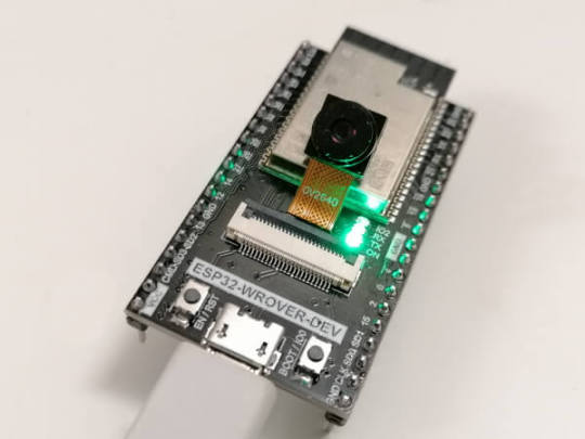
ESP32-CAM WROVER E
In diesem Beitrag möchte ich dir eine weitere ESP32-CAM vorstellen und zeigen, wie du diese programmierst.

Eine ESP32-CAM habe ich dir bereits im Beitrag Einrichten der ESP32-CAM und erster betrieb vorgestellt und auch gezeigt, wie du diese in der Arduino IDE programmierst.


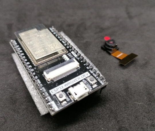
Bezug der ESP32-CAM WROVER DEV
Die mir vorliegende ESP32-CAM habe ich recht günstig über aliexpress.com für knapp 7 € zzgl. Versandkosten erstanden. Du findest die coole ESP32-CAM auch auf amazon.de für knapp 35 € als Set mit diversen Sensoren / Aktoren. Lieferumfang Zum Lieferumfang der ESP32-CAM gehört neben dem Mikrocontroller noch ein kleine 66° Kameralinse vom Typ OV2640.

Anschluss der ESP32-CAM
Der Anschluss an den Computer erfolgt über eine Micro-USB Schnittstelle. In meinem Fall war kein passendes Kabel dabei (jedoch im verlinkten Amazon Produkt ist es enthalten). Im Geräte-Manager von Microsoft Windows 10 wird der Mikrocontroller als "USB-SERIAL CH340" angezeigt.
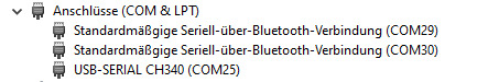
Geräte-Manager von Windows 10 mit angeschlossener ESP32-CAM Während des Betriebs der ESP32-CAM leuchtet eine kleine grüne SMD LED.
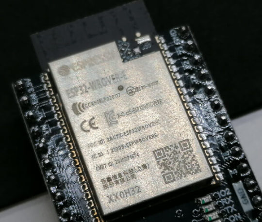
Technische Daten des ESP32 WROVER E
Hier nun ein kleiner Auszug aus den technischen Daten des ESP32 WROVER E. MicrochipESP32-D0WD-V3 Xtensa 32bit LX6Taktgeschwindigkeit240 MHzROM448 KBSRAM520 KBSRAM (in RTC)8 KBPSRAM8 MBSPI flash4 MBWiFiProtokolle - 802.11 b/g/n (802.11n bis zu 150 Mbps)Frequenzbereich - 2412 ~ 2484 MHzBluetoothProtokolle - Bluetooth v4.2 BR/EDR und Bluetooth LE (Low Energy)FeaturesUART, SPI, I²C, LED, PWM, Motor PWM, I²S, IR, Puls Counter, GPIO, kapazitiver Touch Sensor, ADC, DAC, TWAI (Two-Wire Automotive Interface), kompatibel mit ISO11898-1 (CAN-Bus Spezifikation 2.0)Hall SensorSpannungsaufnahme3.0 V ~ 3.6 VStromaufnahme500 mABetriebstemperatur-40 °C ~ 85 °C Im englischen Dokument ESP32WROVERE Datasheet findest du eine ausführliche Liste mit den technischen Daten zum ESP32 WROVER E.
Programmieren in der Arduino IDE
Das ESP32-CAM Beispiel aus der ESP32 Bibliothek beinhaltet eigentlich auch die Konfiguration für das vorliegende Modell, jedoch ist das Kompilat 10 % größer als der verfügbare Speicher des ESP32. text section exceeds available space in boardDer Sketch verwendet 1431461 Bytes (109%) des Programmspeicherplatzes. Das Maximum sind 1310720 Bytes. Globale Variablen verwenden 65344 Bytes (19%) des dynamischen Speichers, 262336 Bytes für lokale Variablen verbleiben. Das Maximum sind 327680 Bytes. Sketch too big; see https://support.arduino.cc/hc/en-us/articles/360013825179 for tips on reducing it. Fehler beim Kompilieren für das Board ESP32 Wrover Module. Auf der Seite https://freenove.com/fnk0060/ findest du eine ZIP-Datei mit allem, was du benötigst, um den ESP32 CAM vom Typ WROVER E zu programmieren und unter anderem ist dort auch eine komprimierte Version enthalten. Zum einen hat der vorliegende Mikrocontroller kein SD-Karten Slot und somit benötigen wir diese Konfiguration inkl. Bibliothek nicht.
Webinterface
Bevor du das Beispiel aus dem Ordner "Freenove_ESP32_WROVER_Board-mainCSketchesSketch_05.1_CameraWebServerSketch_05.1_CameraWebServer.ino" auf den ESP32 speicherst musst du lediglich die SSID & das Passwort von deinem WiFi Netzwerk eintragen. const char *ssid_Router = "********"; //input your wifi name const char *password_Router = "********"; //input your wifi passwords Während des Uploads musst, du, wenn die Ausgabe mit den vielen Punkten erscheint die Taste "EN/RST" betätigen und der Upload wird ausgeführt. Nachdem erfolgreichen Upload kannst du im seriellen Monitor der Arduino IDE die IP-Adresse des Mikrocontrollers ablesen. Über diese IP-Adresse kannst du das Webinterface erreichen und einen Stream deiner ESP32-CAM betrachten und auch Bilder speichern.

Webinterface der neuen ESP32-CAM von 2022
Vergleich mit dem Vorgängermodell
Wie bereits erwähnt habe ich dem Vorgängermodell bereits einige Beiträge gewidmet und auch gezeigt, wie du die Bilder / den Videostream per Python abgreifst und speichern kannst. Da das neue Modell sehr ähnlich funktioniert, kannst du die Beiträge auf den Mikrocontroller adaptieren.
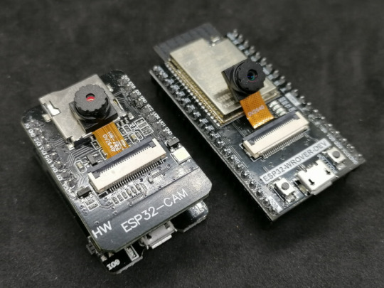
ESP32-CAM Modelle Was zunächst auffällt ist, das die neue ESP32-CAM ohne SD-Card Slot und LED Blitz daherkommt, jedoch bietet diese deutlich mehr GPIO Pins und somit kann man diese recht einfach nachrüsten. Zusätzlich bietet die neue ESP32-CAM vom Typ WROVER E einen onboard FTDI Chip CH340 welcher durch die vorhandene Micro-USB Buchse ohne ein zusätzliches, externes FTDI Modul t die Programmierung ermöglicht. Beim Vorgängermodell wurde dieses mit einem speziellen Board gelöst, auf welches der Mikrocontroller gesteckt wurde.
Vergleich der technischen Daten
Hier ein kleiner Vergleich der technischen Daten der beiden Mikrocontroller. ESP32-CAMESP32 WROVER E CAMMicrochip32Bit Dual Core CPU ESP32-D0WD-V3 Xtensa 32bit LX6Taktgeschwindigkeit240 MHz240 MHzPSRAM4 MB8 MBSPI flash4 MB4 MBWiFi802.11 b/g/n/e/i802.11 b/g/n (802.11n bis zu 150 Mbps)BluetoothBluetooth v4.2 BR/EDR und Bluetooth LE (Low Energy)Bluetooth v4.2 BR/EDR und Bluetooth LE (Low Energy)FeaturesUART, SPI, PWM, GPIO, kapazitiver Touch Sensor, ADC & DACUART, SPI, I²C, LED, PWM, Motor PWM, I²S, IR, Puls Counter, GPIO, kapazitiver Touch Sensor, ADC, DAC, TWAI (Two-Wire Automotive Interface), kompatibel mit ISO11898-1 (CAN-Bus Spezifikation 2.0)Auszug aus den technischen Daten der ESP32-CAMs Read the full article
0 notes
Text
Shootout: Pi Pico vs ESP32(-S2) and STM32 Blackpill
Shootout: Pi Pico vs ESP32(-S2) and STM32 Blackpill
Shootout: Pi Pico vs ESP32(-S2) and STM32 Blackpill Category Main Description: The Raspberry Pi foundation spent a lot of money to create a new chip for makers and gives it away for cheap. If I believe all the fanboy’s videos, it is the most … TopTrengingTV Hunting the most trend video of the moment, every hour every day 24/7. Youtube Video Data Published At: 2021-01-31T08:00:07Z Tags: …

View On WordPress
#arduino#arduino project#beginners#Comparison#diy#do-it-yourself#eevblog#electronics#esp32#esp32 datasheet#esp32 project#esp32 tutorial#ESP32-S2#esp8266#esp8266 datasheet#esp8266 project#greatscott#guide#hack#hobby#how to#IOT#lorawan#main#nodemcu#Pi pico#project#Raspberry Pi#raspberry Pi Pico#RISC-V
0 notes
Text
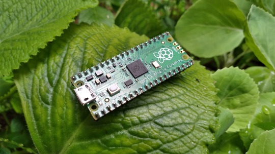
Raspberry Pi Pico: Vale a pena aprender?
Aprenda como usar todos os periféricos do Raspberry Pi Pico, Como instalar bibliotecas no Thonny IDE e ainda veja um comparativo do Pico/Pico W com ESP32, tudo em um único post. Mais completo que isso somente o datasheet.
O Raspberry Pi Pico desde o lançamento vem sendo muito desejado por muitos projetistas, mas será que realmente vale a pena aprender? Neste post você vai aprender tudo sobre ele. 1 Surgimento do Raspberry Pi Pico Quem acompanha a empresa Raspberry Pi, sabe que todos seus lançamentos tem um preço base para um determinado produto e o propósito disso é democratizar ao máximo o acesso aos produtos…
Ver no WordPress
#arduino nano vs raspberry pi pico#arduino raspberry pi pico i2c#arduino vs raspberry pi pico#como programar raspberry pi pico#pico raspberry pi#raspberry pi pico#raspberry pi pico adc#raspberry pi pico analog to digital#raspberry pi pico battery#raspberry pi pico datasheet#raspberry pi pico documentation#raspberry pi pico especificações#raspberry pi pico examples#raspberry pi pico pinout#thonny raspberry pi pico
1 note
·
View note
Text
Tree moisture meters
I had an interesting time last week attending the 4th Trees, People and the Built Environment (TPBE4) conference run by the Chartered Foresters. Some interesting sessions and worthy sentiments but I didnt get any sense of urgency.
A couple of the sessions addressed the use of technology in the urban forest. For example Nadina Galle talked about the Internet of Nature and the application of Smart City thinking, a city-wide network of sensors using AI to make better decisions about deployment of resources. GreenCityWatch have developed tools to create an inventory of urban trees using commercial high-resolution imagery and some open-source image analysis tools. Treemania aims to provide a network of moisture sensors to alert council staff to the need to water newly planted trees.
I have a love-hate relationship with these ideas. On the one hand they too often seem like expensive, irrelevant and authoritarian structures, all bright and shiny to lure unsuspected city councils desparate to show they are doing something towards the climate emergency. On the other hand, I’m a bit of a geek and love the idea of sensors to bring the life of trees to wider notice. Moisture sensors also fit well with a planned platform to assist citizens to look after new trees, in particular 590 trees being planted in deprived areas of Bristol, part-funded by the Urban Tree Challenge Fund.
Treemania’s sensor seemed from the pictures to use a common capacitive moisture sensor. I thought a remote sensor could be based on a board I’ve planned to use on the boat for remote sensing of water level and battery state. I’ve also been looking at it as a basis for a remote dendrometer. The board is an ESP32 with integrated GSM module, costing £15 or less. GSM (2G) is expected to continue to be supported in the UK through to 2025. Rui Santos has a great tutorial on using this board with Arduino code for just such a project. A capacitive soil moisture sensor costs a few quid, a temperature sensor likewise. The board has an integrated socket and charger for a 3.7v LiPo battery. In use the sensor will only need to report at a very low frequency - maybe only a few times a day, and with the ESP deep sleep mode the device should run unattended for a month or more. Soak testing is underway.
Acquiring a suitable SIM is challenging. Although mobile internet on a pay-monthly contract is down to £1 a Gb, minimum payment is around £10 a month. Given that only a Kb or so is used for a single HTTP GET to transmit the data, the device needs only a few Mbs a month. I found a couple of companies specialising in IoT connectivity. The cheapest is ThingsMobile, based in Milan and the cost is more like £10 per annum. Even here, the cost per Mb is 100s of times more expensive than your regular Pay monthly sim. It took ages to arrive but works fine and at E0.12 / Mb is pretty good.
So the bill of materials is:
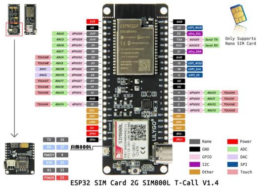
TTGO T-Call ESP32 SIM800L board
Capacitive Moisture Sensor
DS18B20 Waterproof Digital sensor
3.7v LiPo
waterproof container
Overall cost for the components should be under £40.
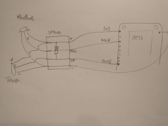
Wiring is straightforward: The moisture meter needs 3.3v power and an A2D pin (ADC0) ; the thermometer is a one-wire interface needed a digital I/O pin (Pin25) with a 4K7 pull-up resistor. Rui also has a great tutorial on interfacing this sensor. I got stuck for a while on this, not realising which GPIO pins supported I/O. Accurate pin-out diagrams and the datasheet for the right variant of board are essential. A small auxiliary veroboard wired directly to the ESP32 board handles these connections. The ESP32 board is supplied with a simple aerial which worked fine. A better quality aerial costs a few quid.
This is the current lashup

Rough sketch of wiring: R is 4K7
The Arduino script hard-codes the GPRS parameters, the HTTP parameters to use GET to send the data to the server and the sleep interval. This code is on GitHub
Periodic readings are sent to my server where they are logged and graphed and from where alerts can be generated. A test harness only at present so nothing worth sharing yet.
Summary
The prototype is working. The moisture sensor needs good waterproofing and seems a bit sensitive to placement. The power draw of the GSM is quite high high during transmission. I’m also running a WiFi version and of course its power draw is much less. It would be nice if the Bristol LoRaWAN network was up and running but that seems to have gone very quiet.
The main problem is with power. This board includes a (very small) JST connector for a LiPo and a charger, For a while it switched happily from USB power to battery and back without manual intervention. LiPos are small and expensive however and I’m currenly experimenting with 18650 batteries which offer better storage/£ .
References
T-Call pinout
ESP32-WROVER datasheet
TTGO T-Call on GitHub
1 note
·
View note
Text
ESP32: ILI9341 Hello world
ESP32: ILI9341 Hello world
Introduction In this tutorial we are going to learn how to write text to a ILI9341 display using the ESP32 and the Arduino core. Note that the ILI9341 is actually the LCD driver (you can check the datasheet here) but, for simplicity, we will refer to the display using this name. In my case, I’m using a 2.4″ TFT display, with 240×320 pixels, bought at eBay. There are a lot of Arduino libraries…
View On WordPress
0 notes
Text
A Tiny LED Matrix is Better With Friends
When we last heard from [lixielabs] he was building Nixie tube replacements out of etched acrylic and LEDs. Well he’s moved forward a few decades to bring us the Pixie, a chainable, addressable backpack for tiny LED matrix displays.
Each Pixie module is designed to host two gorgeous little Lite-On LTP-305G/HR 5×7 LED dot matrix displays, which we suspect have been impulse purchases in many a shopping cart. Along with the displays there is a small matrix controller and an ATTINY45 to expose a friendly electrical interface. Each module is designed to be mounted edge to edge and daisy chained out to 12 or more (with two displays each) for a flexible display any size you need. But to address the entire array only two control pins are required (data and clock).
[lixielabs] has done the legwork to make using those pins as easy as possible. He is careful to point out the importance of a good SDK and provides handy Arduino libraries for common microcontrollers and a reference implementation for the Raspberry Pi that should be easy to crib from to support new platforms. To go with that library support is superb documentation in the form of a datasheet (complete with dimensions and schematic!) and well stocked GitHub repo with examples and more.
To get a sense of their graphical capabilities, check out a video of 6 Pixie’s acting as a VU meter after the break. The Pixie looks like what you get when a hacker gets frustrated at reinventing LED dot matrix control for every project and decided to solve it once and for all. The design is clean, well documented, and extremely functional. We’re excited to see what comes next!
ESP32 with an I2S mic running FFT with 1024 cells, with each octave overlaid to make a 12-note chromagram, being rendered live by Pixies!https://t.co/0nWQfX0W6W pic.twitter.com/UZgh5ymWAw
— Lixie Labs (@lixielabs) September 22, 2020
A Tiny LED Matrix is Better With Friends was originally published on PlanetArduino
0 notes